
主管单位:中国科学技术协会
主办单位:中国兵工学会
ISSN 1000-1093 CN 11-2176/TJ
主办单位:中国兵工学会
ISSN 1000-1093 CN 11-2176/TJ
兵工学报 ›› 2023, Vol. 44 ›› Issue (2): 437-451.doi: 10.12382/bgxb.2021.0561
牛草1,2, 顾广鑫1, 朱磊1, 徐宏斌1,*( ), 李正宇1, 张卫红2, 陈永伟1, 王博1, 石建雄1, 李一哲1
收稿日期:2021-08-23
上线日期:2022-06-08
通讯作者:
基金资助:
NIU Cao1,2, GU Guangxin1, ZHU Lei1, XU Hongbin1,*(), LI Zhengyu1, ZHANG Weihong2, CHEN Yongwei1, WANG Bo1, SHI Jianxiong1, LI Yizhe1
Received:2021-08-23
Online:2022-06-08
摘要:
发射架是车载发射装置的关键承力构件之一,其结构刚度和固有频率等静动力学特性对导弹发射精度具有重要影响。以某车载导弹发射架为研究对象,通过多种行军过载和载弹工况的有限元建模与分析对比,研究发射架的受载特点,提出导弹装填、卸载和发射作业序列规划的一般指导原则。进而对发射架结构进行多工况条件下的拓扑优化,讨论挤压约束、最小和最大尺寸约束对拓扑优化结果的影响。根据拓扑优化构型对发射架进行重构设计,对优化设计进行有限元校核分析。分析结果表明,与原有设计相比,拓扑优化设计后的发射架结构减重超过10%,且几乎所有考虑工况下的刚强度均得到改善,刚度最大增幅达到21.47%,等效应力最大降幅达到31.97%;前6阶固有频率提升超过12%,对于减小发射扰动具有重要意义。
中图分类号:
牛草, 顾广鑫, 朱磊, 徐宏斌, 李正宇, 张卫红, 陈永伟, 王博, 石建雄, 李一哲. 车载导弹发射架结构有限元分析与拓扑优化设计[J]. 兵工学报, 2023, 44(2): 437-451.
NIU Cao, GU Guangxin, ZHU Lei, XU Hongbin, LI Zhengyu, ZHANG Weihong, CHEN Yongwei, WANG Bo, SHI Jianxiong, LI Yizhe. Finite Element Structural Analysis and Topology Optimization of a Vehicle-borne Missile Launching Cradle[J]. Acta Armamentarii, 2023, 44(2): 437-451.

图1 某车载导弹发射装置[2]
Fig.1 A vehicle-borne weapon launcher[2]
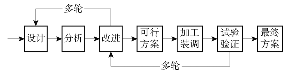
图2 武器装备结构传统设计流程
Fig.2 Traditional structural design process for weapons
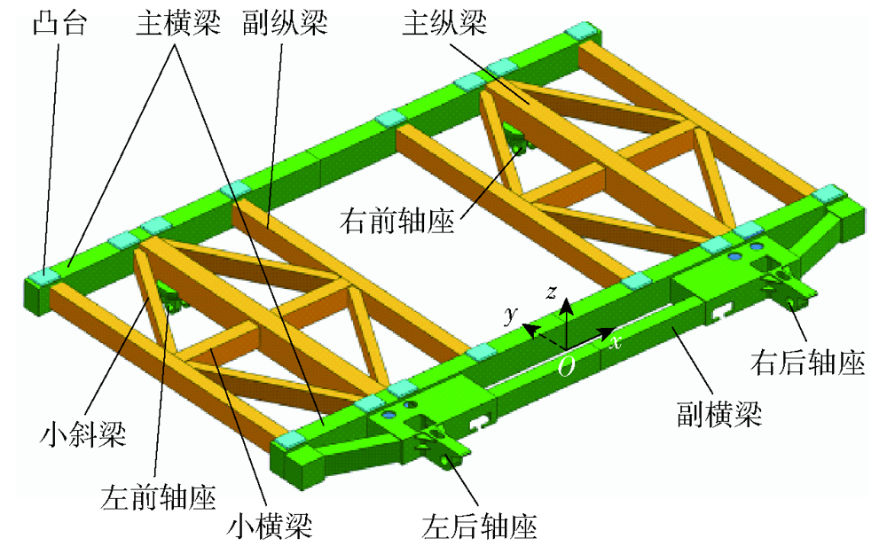
图3 发射架结构原有设计
Fig.3 Original design of the launching cradle
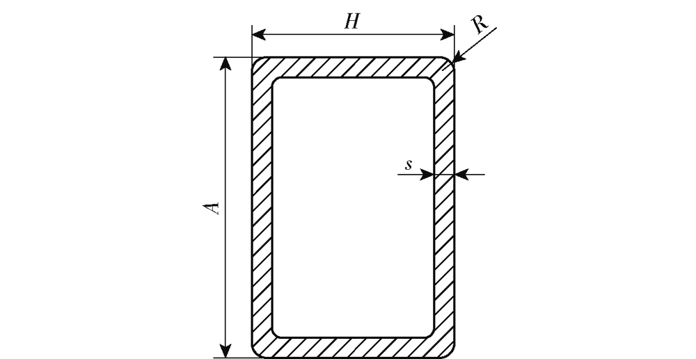
图4 GB/T 3094—2012规定的矩形钢管型材截面
Fig.4 Cross-section of the profiled steel tubes in accordance with GB/T 3094—2012
| 工况编号 | 工况简称 | 加速度分量 | ||
|---|---|---|---|---|
| x轴 | y轴 | z轴 | ||
| 1 | 仅重力 | 0 | 0 | -1g |
| 2 | 垂向-5g | 0 | 0 | -6g |
| 3 | 垂向+5g | 0 | 0 | +4g |
| 4 | 横向-5g | -5g | 0 | -1g |
| 5 | 横向+5g | +5g | 0 | -1g |
| 6 | 纵向-5g | 0 | -5g | -1g |
| 7 | 纵向+5g | 0 | +5g | -1g |
表1 发射架过载工况
Table 1 Overloading conditions of the launching cradle
| 工况编号 | 工况简称 | 加速度分量 | ||
|---|---|---|---|---|
| x轴 | y轴 | z轴 | ||
| 1 | 仅重力 | 0 | 0 | -1g |
| 2 | 垂向-5g | 0 | 0 | -6g |
| 3 | 垂向+5g | 0 | 0 | +4g |
| 4 | 横向-5g | -5g | 0 | -1g |
| 5 | 横向+5g | +5g | 0 | -1g |
| 6 | 纵向-5g | 0 | -5g | -1g |
| 7 | 纵向+5g | 0 | +5g | -1g |
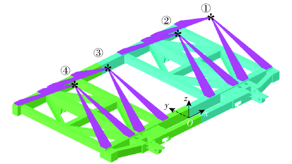
图5 发射架结构原有设计在载弹工况(a)时的有限元模型(“*”表示所承载导弹的等效质量点)
Fig.5 Finite element (FE) model of the original design of the launching cradle under the missile-carrying condition (a) (The asterisks “*” indicates the equivalent mass points of the borne missiles and the same would apply hereinafter)
图6 发射架有限元模型的位移边界条件(“*”表示所承载导弹的等效质量点)
Fig.6 Displacement boundary conditions of the FE model for the launching cradle
| 过载 工况 | 载弹工况 | ||||
|---|---|---|---|---|---|
| (a) | (b) | (d) | (f) | (h) | |
| 1 | 0.1309 | 0.1254 | 0.1497 | 0.1442 | 0.1480 |
| 2 | 0.7855 | 0.7527 | 0.8982 | 0.8653 | 0.8882 |
| 3 | 0.5237 | 0.5018 | 0.5988 | 0.5769 | 0.5921 |
| 4 | 1.3867 | 1.4995 | 1.5797 | 1.6927 | 1.1571 |
| 5 | 1.3867 | 1.3630 | 1.3705 | 1.5047 | 1.1571 |
| 6 | 0.5010 | 0.4972 | 0.5326 | 0.5284 | 0.4723 |
| 7 | 0.6378 | 0.5982 | 0.6537 | 0.6537 | 0.6510 |
表3 载弹工况(a)~(h)下发射架原有设计结构变形
Table 3 Structural deformations of the original launching cradle under the missile-carrying conditions (a)~(h) mm
| 过载 工况 | 载弹工况 | ||||
|---|---|---|---|---|---|
| (a) | (b) | (d) | (f) | (h) | |
| 1 | 0.1309 | 0.1254 | 0.1497 | 0.1442 | 0.1480 |
| 2 | 0.7855 | 0.7527 | 0.8982 | 0.8653 | 0.8882 |
| 3 | 0.5237 | 0.5018 | 0.5988 | 0.5769 | 0.5921 |
| 4 | 1.3867 | 1.4995 | 1.5797 | 1.6927 | 1.1571 |
| 5 | 1.3867 | 1.3630 | 1.3705 | 1.5047 | 1.1571 |
| 6 | 0.5010 | 0.4972 | 0.5326 | 0.5284 | 0.4723 |
| 7 | 0.6378 | 0.5982 | 0.6537 | 0.6537 | 0.6510 |
| 过载 工况 | 载弹工况 | |||
|---|---|---|---|---|
| (i) | (j) | (l) | (n) | |
| 1 | 0.1289 | 0.1237 | 0.1426 | 0.0828 |
| 2 | 0.7736 | 0.7420 | 0.8554 | 0.4968 |
| 3 | 0.5157 | 0.4947 | 0.5702 | 0.3312 |
| 4 | 0.3415 | 1.0766 | 1.2703 | 0.4321 |
| 5 | 0.3415 | 0.8843 | 1.0261 | 0.5296 |
| 6 | 0.4290 | 0.4342 | 0.4681 | 0.2535 |
| 7 | 0.5431 | 0.5513 | 0.6089 | 0.3234 |
表4 载弹工况(i)~(n)下发射架原有设计结构变形
Table 4 Structural deformations of the original launching cradle design under missile-carrying conditions (i)~(n)mm
| 过载 工况 | 载弹工况 | |||
|---|---|---|---|---|
| (i) | (j) | (l) | (n) | |
| 1 | 0.1289 | 0.1237 | 0.1426 | 0.0828 |
| 2 | 0.7736 | 0.7420 | 0.8554 | 0.4968 |
| 3 | 0.5157 | 0.4947 | 0.5702 | 0.3312 |
| 4 | 0.3415 | 1.0766 | 1.2703 | 0.4321 |
| 5 | 0.3415 | 0.8843 | 1.0261 | 0.5296 |
| 6 | 0.4290 | 0.4342 | 0.4681 | 0.2535 |
| 7 | 0.5431 | 0.5513 | 0.6089 | 0.3234 |
| |
表5 原有设计在载弹工况(a)下的有限元分析结果云图
Table 5 Contour plots of finite element analysis (FEA) results of the original design under the missile-carrying condition (a)
| |
图7 发射架原有设计在不同过载和载弹工况下结构变形对比
Fig.7 Comparison of structural deformations of the original launching cradle under different overloading and missile-carrying conditions
| 过载 工况 | 载弹工况 | ||||
|---|---|---|---|---|---|
| (a) | (b) | (d) | (f) | (h) | |
| 1 | 23.06 | 24.10 | 21.46 | 22.49 | 15.11 |
| 2 | 138.38 | 144.59 | 128.76 | 134.97 | 90.67 |
| 3 | 92.26 | 96.40 | 85.84 | 89.98 | 60.45 |
| 4 | 184.98 | 149.80 | 155.64 | 152.83 | 111.07 |
| 5 | 184.98 | 135.04 | 143.32 | 135.05 | 111.06 |
| 6 | 143.33 | 140.69 | 130.85 | 133.21 | 77.11 |
| 7 | 176.76 | 173.40 | 163.37 | 160.00 | 85.02 |
表6 载弹工况(a)~(h)下发射架原有设计等效应力
Table 6 Equivalent stresses of the original launching cradle under the missile-carrying conditions (a)~(h) MPa
| 过载 工况 | 载弹工况 | ||||
|---|---|---|---|---|---|
| (a) | (b) | (d) | (f) | (h) | |
| 1 | 23.06 | 24.10 | 21.46 | 22.49 | 15.11 |
| 2 | 138.38 | 144.59 | 128.76 | 134.97 | 90.67 |
| 3 | 92.26 | 96.40 | 85.84 | 89.98 | 60.45 |
| 4 | 184.98 | 149.80 | 155.64 | 152.83 | 111.07 |
| 5 | 184.98 | 135.04 | 143.32 | 135.05 | 111.06 |
| 6 | 143.33 | 140.69 | 130.85 | 133.21 | 77.11 |
| 7 | 176.76 | 173.40 | 163.37 | 160.00 | 85.02 |
| 过载 工况 | 载弹工况 | |||
|---|---|---|---|---|
| (i) | (j) | (l) | (n) | |
| 1 | 16.07 | 16.22 | 15.76 | 13.08 |
| 2 | 96.41 | 97.33 | 94.54 | 78.46 |
| 3 | 64.27 | 64.89 | 63.02 | 52.30 |
| 4 | 92.98 | 105.45 | 108.38 | 60.77 |
| 5 | 92.98 | 97.50 | 90.01 | 63.62 |
| 6 | 108.51 | 95.34 | 79.47 | 92.70 |
| 7 | 115.10 | 105.07 | 81.65 | 101.70 |
表7 载弹工况(i)~(n)下发射架原有设计等效应力
Table 7 Equivalent stresses of the original launching cradle under the missile-carrying conditions (i)~(n) MPa
| 过载 工况 | 载弹工况 | |||
|---|---|---|---|---|
| (i) | (j) | (l) | (n) | |
| 1 | 16.07 | 16.22 | 15.76 | 13.08 |
| 2 | 96.41 | 97.33 | 94.54 | 78.46 |
| 3 | 64.27 | 64.89 | 63.02 | 52.30 |
| 4 | 92.98 | 105.45 | 108.38 | 60.77 |
| 5 | 92.98 | 97.50 | 90.01 | 63.62 |
| 6 | 108.51 | 95.34 | 79.47 | 92.70 |
| 7 | 115.10 | 105.07 | 81.65 | 101.70 |
图8 发射架拓扑优化有限元模型(黄色部分为设计域,绿色部分为非设计域)
Fig.8 FE model for topology optimization of the launching cradle (The regions in yellow are designable while those in green are not)
图9 无制造约束的拓扑优化构型
Fig.9 Optimized topological configuration without manufacturing constraints
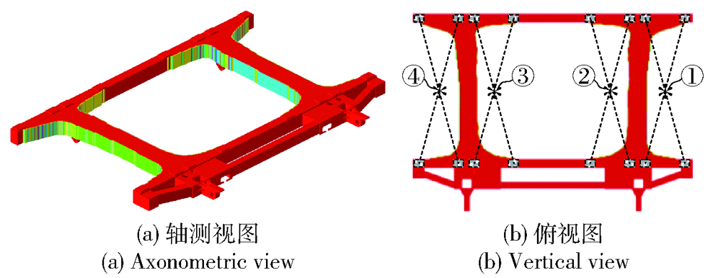
图10 施加挤压约束的拓扑优化构型
Fig.10 Optimized topological configuration with extrusion constraints
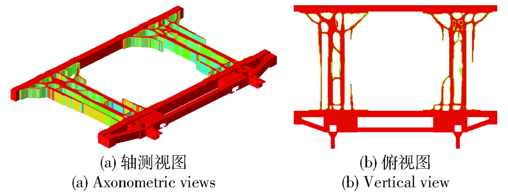
图11 同时施加挤压约束和尺寸约束的拓扑优化构型:最小尺寸约束30mm,最大尺寸约束120mm
Fig.11 Optimized topological configuration with extrusion constraints (minimum member size constraint at 30mm and maximum at 120mm)

图12 同时施加挤压约束和尺寸约束的拓扑优化构型:最小尺寸约束40mm,最大尺寸约束120mm
Fig.12 Optimized topological configuration with extrusion constraints (minimum member size constraint at 40mm and maximum at 120mm)
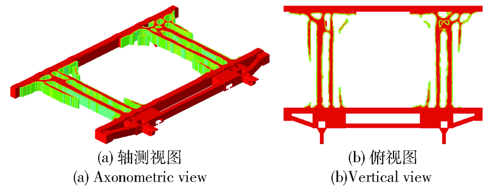
图13 同时施加挤压约束和尺寸约束的拓扑优化构型:最小尺寸约束60mm,最大尺寸约束120mm
Fig.13 Optimized topological configuration with extrusion constraints (minimum member size constraint at 60mm and maximum at 120mm)
| 挤压 约束 | 最小尺寸 约束/mm | 最大尺寸 约束/mm | 加权柔顺 度/J | 体分比 | 迭代 步数 |
|---|---|---|---|---|---|
| 50.38 | 0.25 | 31 | |||
| √ | 59.90 | 0.25 | 36 | ||
| √ | 30 | 120 | 69.27 | 0.25 | 60 |
| √ | 40 | 120 | 71.89 | 0.25 | 74 |
| √ | 60 | 120 | 76.54 | 0.25 | 72 |
表8 拓扑优化迭代过程数据
Table 8 Statistical data of the topology optimization processes
| 挤压 约束 | 最小尺寸 约束/mm | 最大尺寸 约束/mm | 加权柔顺 度/J | 体分比 | 迭代 步数 |
|---|---|---|---|---|---|
| 50.38 | 0.25 | 31 | |||
| √ | 59.90 | 0.25 | 36 | ||
| √ | 30 | 120 | 69.27 | 0.25 | 60 |
| √ | 40 | 120 | 71.89 | 0.25 | 74 |
| √ | 60 | 120 | 76.54 | 0.25 | 72 |
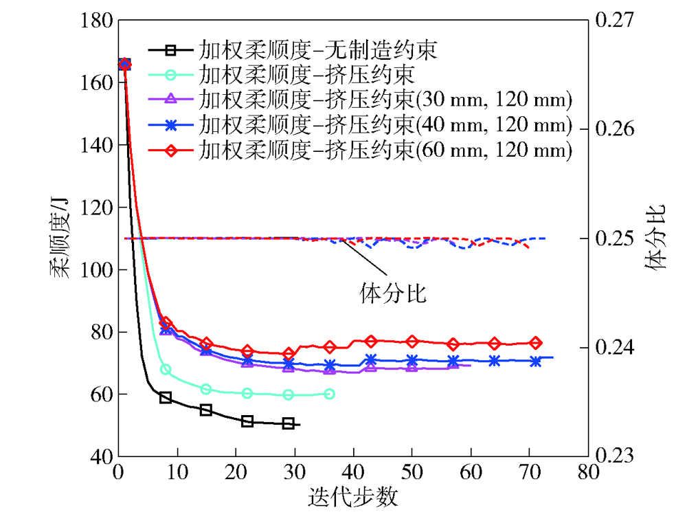
图14 拓扑优化中加权柔顺度和体分比的迭代曲线(圆括号内数字分别表示最小和最大尺寸约束值)
Fig.14 Iterative curves of weighted compliance and volume fraction in topology optimization processes. The numbers in the parentheses indicate the values of the minimum and maximum member size constraints, respectively
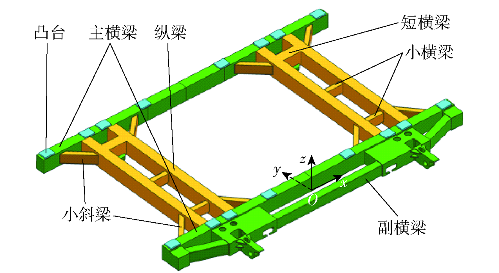
图15 根据拓扑优化结果重构的发射架优化设计模型
Fig.15 Reconstructed model of the launching cradle based on the topology optimization results
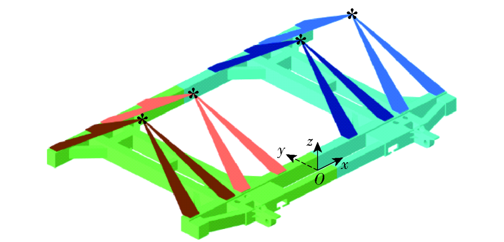
图16 发射架优化设计有限元校核分析模型
Fig.16 FE model of the optimized design for verification
| 过载 工况 | 载弹工况 | ||||
|---|---|---|---|---|---|
| (a) | (b) | (d) | (f) | (h) | |
| 1 | 0.1198 ↓8.48% | 0.1150 ↓8.29% | 0.1372 ↓8.35% | 0.1323 ↓8.25% | 0.1363 ↓7.91% |
| 2 | 0.7190 ↓8.47% | 0.6898 ↓8.36% | 0.8232 ↓8.35% | 0.7940 ↓8.24% | 0.8180 ↓7.90% |
| 3 | 0.4793 ↓8.48% | 0.4599 ↓8.35% | 0.5488 ↓8.35% | 0.5293 ↓8.25% | 0.5453 ↓7.90% |
| 4 | 1.1285 ↓18.62% | 1.1993 ↓20.02% | 1.2635 ↓20.02% | 1.3347 ↓21.15% | 0.9473 ↓18.13% |
| 5 | 1.1285 ↓18.62% | 1.0825 ↓20.58% | 1.0977 ↓19.91% | 1.1817 ↓21.47% | 0.9473 ↓18.13% |
| 6 | 0.4625 ↓7.68% | 0.4605 ↓7.38% | 0.5072 ↓4.77% | 0.4986 ↓5.64% | 0.4781 ↑1.23% |
| 7 | 0.5937 ↓6.91% | 0.5789 ↓3.23% | 0.6195 ↓10.76% | 0.6033 ↓7.71% | 0.5692 ↓12.57% |
表10 载弹工况(a)~(h)下发射架优化设计结构变形
Table 10 Structural deformations of the optimized launching cradle design under the missile-carrying conditions (a)~(h) mm
| 过载 工况 | 载弹工况 | ||||
|---|---|---|---|---|---|
| (a) | (b) | (d) | (f) | (h) | |
| 1 | 0.1198 ↓8.48% | 0.1150 ↓8.29% | 0.1372 ↓8.35% | 0.1323 ↓8.25% | 0.1363 ↓7.91% |
| 2 | 0.7190 ↓8.47% | 0.6898 ↓8.36% | 0.8232 ↓8.35% | 0.7940 ↓8.24% | 0.8180 ↓7.90% |
| 3 | 0.4793 ↓8.48% | 0.4599 ↓8.35% | 0.5488 ↓8.35% | 0.5293 ↓8.25% | 0.5453 ↓7.90% |
| 4 | 1.1285 ↓18.62% | 1.1993 ↓20.02% | 1.2635 ↓20.02% | 1.3347 ↓21.15% | 0.9473 ↓18.13% |
| 5 | 1.1285 ↓18.62% | 1.0825 ↓20.58% | 1.0977 ↓19.91% | 1.1817 ↓21.47% | 0.9473 ↓18.13% |
| 6 | 0.4625 ↓7.68% | 0.4605 ↓7.38% | 0.5072 ↓4.77% | 0.4986 ↓5.64% | 0.4781 ↑1.23% |
| 7 | 0.5937 ↓6.91% | 0.5789 ↓3.23% | 0.6195 ↓10.76% | 0.6033 ↓7.71% | 0.5692 ↓12.57% |
| 过载 工况 | 载弹工况 | |||
|---|---|---|---|---|
| (i) | (j) | (l) | (n) | |
| 1 | 0.1137 ↓11.79% | 0.1140 ↓7.84% | 0.1314 ↓7.85% | 0.0715 ↓13.65% |
| 2 | 0.6821 ↓11.83% | 0.6840 ↓7.82% | 0.7885 ↓7.82% | 0.4290 ↓13.65% |
| 3 | 0.4547 ↓11.83% | 0.4560 ↓7.82% | 0.5257 ↓7.80% | 0.2860 ↓13.65% |
| 4 | 0.2719 ↓20.38% | 0.8827 ↓18.01% | 1.0186 ↓19.81% | 0.3785 ↓13.03% |
| 5 | 0.2719 ↓20.38% | 0.7263 ↓17.87% | 0.8257 ↓19.53% | 0.4317 ↓18.49% |
| 6 | 0.3984 ↓7.13% | 0.4261 ↓1.87% | 0.4696 ↑0.32% | 0.2380 ↓6.11% |
| 7 | 0.5162 ↓4.95% | 0.5282 ↓4.19% | 0.5529 ↓9.20% | 0.3148 ↓2.66% |
表11 载弹工况(i)~(n)下发射架优化设计结构变形
Table 11 Structural deformations of the optimized launching cradle design under the missile-carrying conditions (i)~(n) mm
| 过载 工况 | 载弹工况 | |||
|---|---|---|---|---|
| (i) | (j) | (l) | (n) | |
| 1 | 0.1137 ↓11.79% | 0.1140 ↓7.84% | 0.1314 ↓7.85% | 0.0715 ↓13.65% |
| 2 | 0.6821 ↓11.83% | 0.6840 ↓7.82% | 0.7885 ↓7.82% | 0.4290 ↓13.65% |
| 3 | 0.4547 ↓11.83% | 0.4560 ↓7.82% | 0.5257 ↓7.80% | 0.2860 ↓13.65% |
| 4 | 0.2719 ↓20.38% | 0.8827 ↓18.01% | 1.0186 ↓19.81% | 0.3785 ↓13.03% |
| 5 | 0.2719 ↓20.38% | 0.7263 ↓17.87% | 0.8257 ↓19.53% | 0.4317 ↓18.49% |
| 6 | 0.3984 ↓7.13% | 0.4261 ↓1.87% | 0.4696 ↑0.32% | 0.2380 ↓6.11% |
| 7 | 0.5162 ↓4.95% | 0.5282 ↓4.19% | 0.5529 ↓9.20% | 0.3148 ↓2.66% |
| 过载 工况 | 载弹工况 | ||||
|---|---|---|---|---|---|
| (a) | (b) | (d) | (f) | (h) | |
| 1 | 23.34 ↑1.21% | 24.57 ↑1.95% | 21.48 ↑0.09% | 22.71 ↑0.98% | 14.54 ↓3.77% |
| 2 | 140.04 ↑1.20% | 147.43 ↑1.96% | 128.89 ↑0.10% | 136.27 ↑0.96% | 87.23 ↓3.79% |
| 3 | 93.36 ↑1.19% | 98.28 ↑1.95% | 85.93 ↑0.10% | 90.85 ↑0.97% | 58.15 ↓3.80% |
| 4 | 125.85 ↓31.97% | 125.35 ↓16.32% | 130.49 ↓16.16% | 130.04 ↓14.91% | 86.14 ↓22.45% |
| 5 | 125.85 ↓31.97% | 113.43 ↓16.00% | 119.20 ↓16.83% | 117.63 ↓12.90% | 86.14 ↓22.44% |
| 6 | 130.85 ↓8.71% | 135.18 ↓3.92% | 123.12 ↓5.91% | 127.45 ↓4.32% | 82.45 ↑6.93% |
| 7 | 144.00 ↓18.53% | 145.36 ↓16.17% | 129.64 ↓20.65% | 131.01 ↓18.12% | 72.67 ↓14.53% |
表12 载弹工况(a)~(h)下发射架优化设计等效应力
Table 12 Equivalent stresses of the optimized design under the missile-carrying conditions (a)~(h) MPa
| 过载 工况 | 载弹工况 | ||||
|---|---|---|---|---|---|
| (a) | (b) | (d) | (f) | (h) | |
| 1 | 23.34 ↑1.21% | 24.57 ↑1.95% | 21.48 ↑0.09% | 22.71 ↑0.98% | 14.54 ↓3.77% |
| 2 | 140.04 ↑1.20% | 147.43 ↑1.96% | 128.89 ↑0.10% | 136.27 ↑0.96% | 87.23 ↓3.79% |
| 3 | 93.36 ↑1.19% | 98.28 ↑1.95% | 85.93 ↑0.10% | 90.85 ↑0.97% | 58.15 ↓3.80% |
| 4 | 125.85 ↓31.97% | 125.35 ↓16.32% | 130.49 ↓16.16% | 130.04 ↓14.91% | 86.14 ↓22.45% |
| 5 | 125.85 ↓31.97% | 113.43 ↓16.00% | 119.20 ↓16.83% | 117.63 ↓12.90% | 86.14 ↓22.44% |
| 6 | 130.85 ↓8.71% | 135.18 ↓3.92% | 123.12 ↓5.91% | 127.45 ↓4.32% | 82.45 ↑6.93% |
| 7 | 144.00 ↓18.53% | 145.36 ↓16.17% | 129.64 ↓20.65% | 131.01 ↓18.12% | 72.67 ↓14.53% |
| 过载 工况 | 载弹工况 | |||
|---|---|---|---|---|
| (i) | (j) | (l) | (n) | |
| 1 | 15.10 ↓6.04% | 15.96 ↓1.60% | 15.19 ↓3.62% | 13.23 ↑1.15% |
| 2 | 90.62 ↓6.01% | 95.78 ↓1.59% | 91.12 ↓3.62% | 79.39 ↑1.19% |
| 3 | 60.41 ↓6.01% | 63.86 ↓1.59% | 60.75 ↓3.60% | 52.93 ↑1.20% |
| 4 | 54.20 ↓41.71% | 81.01 ↓23.18% | 85.68 ↓20.94% | 53.50 ↓11.96% |
| 5 | 54.20 ↓41.71% | 70.37 ↓27.83% | 72.67 ↓19.26% | 53.46 ↓15.97% |
| 6 | 90.43 ↓16.66% | 86.80 ↓8.96% | 82.20 ↑3.44% | 75.27 ↓18.80% |
| 7 | 98.69 ↓14.26% | 82.97 ↓21.03% | 69.74 ↓14.59% | 84.33 ↓17.08% |
表13 载弹工况(i)~(n)下发射架优化设计等效应力
Table 13 Equivalent stresses of the optimized launching cradle design under the missile-carrying conditions (i)~(n) MPa
| 过载 工况 | 载弹工况 | |||
|---|---|---|---|---|
| (i) | (j) | (l) | (n) | |
| 1 | 15.10 ↓6.04% | 15.96 ↓1.60% | 15.19 ↓3.62% | 13.23 ↑1.15% |
| 2 | 90.62 ↓6.01% | 95.78 ↓1.59% | 91.12 ↓3.62% | 79.39 ↑1.19% |
| 3 | 60.41 ↓6.01% | 63.86 ↓1.59% | 60.75 ↓3.60% | 52.93 ↑1.20% |
| 4 | 54.20 ↓41.71% | 81.01 ↓23.18% | 85.68 ↓20.94% | 53.50 ↓11.96% |
| 5 | 54.20 ↓41.71% | 70.37 ↓27.83% | 72.67 ↓19.26% | 53.46 ↓15.97% |
| 6 | 90.43 ↓16.66% | 86.80 ↓8.96% | 82.20 ↑3.44% | 75.27 ↓18.80% |
| 7 | 98.69 ↓14.26% | 82.97 ↓21.03% | 69.74 ↓14.59% | 84.33 ↓17.08% |
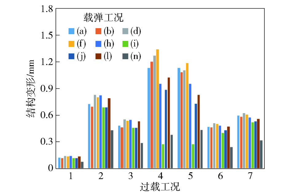
图17 发射架优化设计在不同过载和载弹工况下结构变形对比
Fig.17 Comparison of structural deformations of the optimized launching cradle under different overloading and missile-carrying conditions
| 阶数 | 原有设计/Hz | 优化设计/Hz | 提高幅度 |
|---|---|---|---|
| 1 | 106.16 | 124.09 | 16.89% |
| 2 | 111.73 | 137.57 | 23.13% |
| 3 | 116.68 | 144.63 | 23.95% |
| 4 | 161.02 | 192.48 | 19.54% |
| 5 | 168.11 | 216.68 | 28.89% |
| 6 | 198.89 | 223.19 | 12.22% |
表14 原有设计与优化设计的固有频率对比
Table 14 Comparison of natural frequencies of the original and optimized designs
| 阶数 | 原有设计/Hz | 优化设计/Hz | 提高幅度 |
|---|---|---|---|
| 1 | 106.16 | 124.09 | 16.89% |
| 2 | 111.73 | 137.57 | 23.13% |
| 3 | 116.68 | 144.63 | 23.95% |
| 4 | 161.02 | 192.48 | 19.54% |
| 5 | 168.11 | 216.68 | 28.89% |
| 6 | 198.89 | 223.19 | 12.22% |
| [1] |
《车载武器》编委会. 车载武器[M]. 北京: 航空工业出版社, 2010.
|
|
Editorial Board of Vehicle-borne Weapons. Vehicle-borne weapons[M]. Beijing: Aviation Industry Press, 2010. (in Chinese)
|
|
| [2] |
熊文博. “红箭”来袭——珠海航展上的“红箭”10反坦克导弹[J]. 坦克装甲车辆, 2016(23):31-35.
|
|
|
|
| [3] |
中华人民共和国国务院新闻办公室. 新时代的中国国防[R]. 2019-07-24.
|
|
The State Council Information Office of the People's Republic of China. China's national defense in the new era.[R]. 2019-07-24. (in Chinese)
|
|
| [4] |
张永存, 韩亚鹏, 刘书田. 典型火炮静刚度分析与改进设计[J]. 机械工程学报, 2013, 49(21):100-107.
|
|
|
|
| [5] |
张永存, 吴雪云, 刘书田. 典型火炮结构振动分析与前支架设计改进[J]. 工程力学, 2013, 30(6):308-312.
|
|
|
|
| [6] |
薛海瑞, 徐宏斌, 张东生, 等. 基于混合仿真的某导弹发射架结构仿真分析[J]. 弹箭与制导学报, 2014, 34(5):46-50.
|
|
|
|
| [7] |
|
| [8] |
doi: 10.1007/s00158-013-0978-6 URL |
| [9] |
doi: 10.1007/s11831-015-9151-2 URL |
| [10] |
王金明, 鲍国苗, 刘勇, 等. 新型运载火箭结构优化设计与试验验证[J]. 上海航天, 2021, 38(3):134-146.
|
|
|
|
| [11] |
王显会, 许刚, 李守成, 等. 特种车辆车架结构拓扑优化设计研究[J]. 兵工学报, 2007, 28(8):903-908.
|
|
|
|
| [12] |
张海航, 于存贵, 唐明晶. 某火炮上架结构拓扑优化设计[J]. 弹道学报, 2009, 21(2):83-85,89.
|
|
|
|
| [13] |
孙全兆, 杨国来, 葛建立. 某火炮上架结构改进设计[J]. 兵工学报, 2012, 33(11):1281-1285.
|
|
|
|
| [14] |
孙玲庆, 李志刚, 王思杰. 某火炮翻板机构回转臂的结构优化设计[J]. 兵器装备工程学报, 2021, 42(4):224-227.
|
|
|
|
| [15] |
doi: 10.1016/j.ast.2005.12.006 URL |
| [16] |
|
| [17] |
温晶晶, 吴斌, 刘承骛. 导弹整体式翼面骨架结构的拓扑优化设计[J]. 兵工学报, 2017, 38(1):81-88.
doi: 10.3969/j.issn.1000-1093.2017.01.011 |
|
|
|
| [18] |
杨翠东, 鄢章渝, 韩磊, 等. 火箭武器发射箱结构优化方法及应用[J]. 中北大学学报(自然科学版), 2018, 39(1):61-68.
|
|
|
|
| [19] |
孙延超, 李军, 韩世东, 等. 火箭发射装置回转箱体拓扑优化设计方法研究[J]. 弹箭与制导学报, 2012, 32(1):208-210.
|
|
|
|
| [20] |
刘晴, 李军, 张震, 等. 某火箭炮底架结构的拓扑优化设计[J]. 四川兵工学报, 2015, 36(2):54-56.
|
|
|
|
| [21] |
刘瀚超, 王学智, 李敏, 等. 基于多体动力学的发射装置托架拓扑优化设计[J]. 弹道学报, 2021, 33(1):11-15,22.
|
|
|
|
| [22] |
刘欢, 李韶华, 张培强. 刚柔耦合特种车辆越障行驶动力学分析及悬架优化[J]. 动力学与控制学报, 2021, 19(3):74-82.
|
|
|
|
| [23] |
|
| [24] |
doi: 10.1007/s11831-019-09331-1 |
| [25] |
doi: 10.1007/BF01650949 URL |
| [26] |
doi: 10.1007/s001580050130 URL |
| [27] |
doi: 10.1002/nme.2499 URL |
| [28] |
doi: 10.1016/j.advengsoft.2020.102897 URL |
| [29] |
doi: 10.1007/s00158-012-0803-7 URL |
| [30] |
doi: 10.1007/s00158-008-0250-7 URL |
| [1] | 项新梅, 罗林林, 符祖书, 何世珠. 梯度模式对Miura-ori超材料力学性能影响的研究[J]. 兵工学报, 2024, 45(2): 618-627. |
| [2] | 刘腾, 周雄飞, 王成全, 敬霖. 列车碰撞事故下轮轨动态作用机理与脱轨抑制技术[J]. 兵工学报, 2023, 44(S1): 67-78. |
| [3] | 刘一鸣, 熊自明, 陈曦, 仲思东, 王德荣. 反无人机用空间条网牵引展开仿真与试验研究[J]. 兵工学报, 2022, 43(9): 2048-2057. |
| [4] | 李志农, 曾文钧, 闻庆松, 沈功田, 沈永娜. 静载拉伸和低周疲劳下Q235钢磁声发射特性[J]. 兵工学报, 2021, 42(1): 185-191. |
| [5] | 王鑫, 赵汝岩, 卢洪义, 刘磊, 伍鹏. 基于加速老化和实测载荷的立式贮存固体发动机药柱寿命评估[J]. 兵工学报, 2019, 40(11): 2212-2219. |
| [6] | 田金山, 李德胜, 宁克焱, 方青峰, 叶乐志, 张凯. 面向重型履带车辆的新式电涡流-液力复合型缓速器研究[J]. 兵工学报, 2018, 39(12): 2313-2319. |
| [7] | 姜缪文, 闫健卓, 陈继民. 基于拓扑优化技术的军用头盔内胆结构三维打印[J]. 兵工学报, 2017, 38(9): 1845-1853. |
| [8] | 范光程, 江明阳, 隆小飞, 邓慧敏, 严仲明, 王豫. 驱动线圈连接方式对多极矩电磁发射效率的影响研究[J]. 兵工学报, 2017, 38(4): 643-650. |
| [9] | 温晶晶, 吴斌, 刘承骛. 导弹整体式翼面骨架结构的拓扑优化设计[J]. 兵工学报, 2017, 38(1): 81-88. |
| [10] | 楼俐, 范建华, 徐诚. 基于局部稳定性测度的战术移动自组织网络拓扑优化抗干扰技术研究[J]. 兵工学报, 2016, 37(9): 1662-1669. |
| [11] | 高军强, 汤霞清, 黄湘远, 程旭维. 减振系统造成捷联惯性导航误差的有限元分析方法[J]. 兵工学报, 2016, 37(9): 1570-1577. |
| [12] | 徐笑, 樊黎霞, 王亚平, 董晓彬. 身管精锻过程跨尺度多晶体塑性有限元模拟与织构预测[J]. 兵工学报, 2016, 37(7): 1180-1186. |
| [13] | 杨庆涛, 白菡尘, 张涛, 杨娟, 王辉. 快速响应热流/温度传感器设计与特性分析[J]. 兵工学报, 2014, 35(6): 927-934. |
| [14] | 秦国华, 张运建, 叶海潮. 基于神经网络的薄壁件加工变形预测方法[J]. 兵工学报, 2013, 34(7): 840-845. |
| [15] | 刘健宁, 蒋军彪, 石顺祥, 马家君, 郭强. 棱镜式激光陀螺稳频伺服系统优化分析[J]. 兵工学报, 2013, 34(7): 821-827. |
| 阅读次数 | ||||||
|
全文 |
|
|||||
|
摘要 |
|
|||||
 京公网安备11010802024360号 京ICP备05059581号-4